We will discuss two models of delay that are used in VHDL. The first is called the inertial delay model. The inertial delay model is specified by adding an after clause to the signal assignment statement. For example, suppose that a change on the input of a nor gate would cause the output to change after a delay of 1ns. To model this delay in the SR latch example, we could replace the two signal assignments with the following two statements.
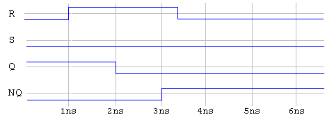
q<=r nor nq after 1ns;
nq<=s nor q after 1ns;
Now during simulation, say signal r changes and will cause the signal q to change, rather than schedule the event on q to occur during the next round, it is scheduled to occur 1ns form the current time. Thus the simulator must maintain a current time value. When no more events exist to be processed at the current time value, time is updated to the time of the next earliest event and all events scheduled for that time will be processed. A timing diagram for this modified SR latch produced by a simulator might be:
Notice the change did not occur in q until 1ns after the change in r. Likewise the change in nq did not occur until 1ns after the change in q. Thus, the "after 1ns" models an internal delay of the nor gate.
However, this is not the end of the story for the inertial delay model. Typically, when a component has some internal delay and an input changes for a time less than this delay, then no change in the output will occur. This is also the case for the inertial delay model. The following timing diagram would be produced using the inertial delay model, if the '1' pulse on the signal r was shortened (to anything less than 1ns) from the previous example.
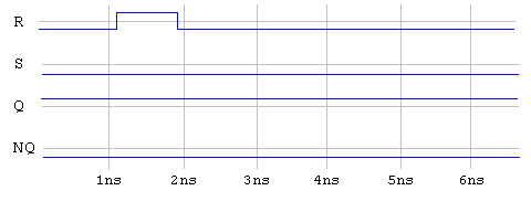
The value of q never changed because the change in r did not last long enough. Said another way, the change in r did not gain enough inertia.
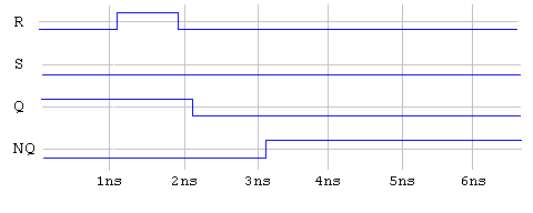
Although most often the inertial delay is desired, sometimes all changes on the input should have an effect on the output. For example, a bus experiences a time delay, but will not "absorb" short pulses as with the inertial delay model. As a result, VHDL provides the transport delay model. The transport delay model just delays the change in the output by the time specified in the after clause. You can elect to use the transport delay model instead of the inertial delay model by adding the keyword transport to the signal assignment statement.
The SR latch example could be modified to use the transport delay model by replacing the signal assignments with the following two statements.
q<=transport r nor nq after 1ns;
nq<=transport s nor q after 1ns;
If the transport delay model were used, the result of the same simulation shown in the last diagram would result in the following timing diagram.
The previous section is Data Flow Descriptions - How it Works.
The next section is Data Flow Descriptions - Other Types.