The VHDL standard not only describes how designs are specified, but also how they should be interpreted. This is the purpose of having standards, so that we can all agree on the meaning of a design. It is important to understand how a VHDL simulator interprets a design because that dictates what the "correct" interpretation is according to the standard (Hopefully, simulators are not all 100% correct).
The scheme used to model a VHDL design is called discrete event time simulation. When the value of a signal changes, we say an event has occurred on that signal. If data flows from signal A to signal B, and an event has occurred on signal A (i.e. A's value changes), then we need to determine the possibly new value of B. This is the foundation of the discrete event time simulation. The values of signals are only updated when certain events occur and events occur at discrete instances of time.
Since one event causes another, simulation proceeds in rounds. The simulator maintains a list of events that need to be processed. In each round, all events in a list are processed, any new events that are produced are placed in a separate list (and are said to be scheduled) for processing in a later round. Each signal assignment is evaluated once, when simulation begins to determine the initial value of each signal.
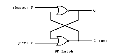
Lets examine how the event time simulation proceeds for the previous example of an SR latch. The following is a schematic version of the SR latch.

The internal operation of the latch was essentially captured using the following two statements.
q<=r nor nq;
nq<=s nor q;
Since data flows from r and nq to q, we say that q depends on r and nq. In general, given any signal assignment statement, the signal on the left side of the <= operator depends on all the signals appearing on the right side. If a signal depends on another signal that an event has occurred on, then the expression in the signal assignment is re-evaluated. If the result of the evaluation is different than the current value of the signal, an event will be scheduled (added to the list of events to be processed) to update the signal with the new value. Thus, if an event occurs on r or nq, then the nor operator is evaluated, and if the result is different than the current value of q, then an event will be scheduled to update q.
Suppose at a particular moment during a simulation of the SR latch example, the values of the signals are s='0',r='0', q='1', and nq='0'. Now suppose the value of the signal r changes (due to some event external to the design) to the value '1'. Since q depends on r, we must re-evaluate the expression r nor nq, which now evaluates to '0'. Since the value of q must be changed to '0', a new event will be scheduled on the signal q. During the next round the event scheduled for q is processed and q's value is updated to be '0'. Also, since nq depends on q, the expression s nor q must be re-evaluated. The result of the expression is '1', so an event is scheduled to update the value of nq. During the next round, when the event on nq is processed, the expression for q will be evaluated again because it depends on nq. However, the result of the expression will be '0' and no new event will be scheduled because q is already '0'. Since, no new events were scheduled, there are no more events that will occur internally to the latch.
Now, suppose an external event causes r to return to the value '0'. Since q depends on r, r nor nq is evaluated again. The result of this expression is '0' and q is already '0', so no events are scheduled. As you can see, this correctly models the SR latch as we would expect. When the signal r became active ('1') the output of the latch was reset, and when r became inactive ('0') the output remained unchanged.
The simulation rounds described in these last two paragraphs can be summarized as follows.
start  : r='0',s='0',q='1',nq='0'
round 1: r='1',s='0',q='1',nq='0', The value '0' is scheduled on q.
round 2: r='1',s='0',q='0',nq='0', The value '1' is scheduled on nq.
round 3: r='1',s='0',q='0',nq='1', No new events are scheduled.
round 4: r='0',s='0',q='0',nq='1', No new events are scheduled.
The previous section is Data Flow Descriptions - A First Example.